I've been assembling an SO-ARM101 robot arm lately. After thinking about which configuration to buy, I decided to go with the basic setup: buy the printed parts and servo motors, then choose the cameras separately.
Today I want to share one small compatibility problem I ran into along the way—and the part I designed to get around it.
Why choose the cameras separately?
The printed structural parts and servos are enough to assemble the arm itself. Some complete kits bundle cameras too, but I decided to keep that choice separate this time:
- Printed parts: the base, links, gripper, and the rest of the arm structure.
- Servo motors: the set that drives the joints.
- Cameras: left out of my basic purchase and sourced separately.
My reasoning was simple. If I was going to swap to the sensor I wanted later anyway, why not start with my preferred module? Besides, there's a certain pleasure in making life harder for yourself. Hahaha.
And then the camera didn't fit
This is where the trouble started. The SO-ARM101 camera mount I was working from was designed for a 32 × 32 mm camera board. I bought a module using an IMX307 sensor, then discovered that its board was 38 × 38 mm.
Ah yes. This is the experience I signed up for!
That size describes the particular board I bought, not every camera with an IMX307 sensor. The sensor name alone doesn't tell you the board dimensions or mounting-hole positions.
I looked for a mount already adapted to a 38 × 38 mm IMX307 module and the SO-ARM101, but couldn't find a suitable one. Maybe I just missed it. Either way, I decided to design my own.
A printed mount for the 38 × 38 mm board
I kept the part that mates with the original robot-side attachment and redesigned the camera mounting face for my larger board. There are four mounting holes, with 34 mm between their centres in both directions.
I tried to follow the original mount's shape as closely as possible, so I wouldn't need to modify the arm-side attachment when installing it.
I also made a separate holder for a ball head or tripod with a 1/4-20 camera screw. That holder takes a metal 1/4-20 nut: the nut provides the thread, rather than a thread printed directly into the plastic.
From the printer to the wrist
When I printed and installed the wrist mount, the spare screws from the motor box went straight in without any extra work. I'd been a little worried about whether the screws would fit, so that part was easier than expected. A small win!
To remove some play after assembly, I put one layer of double-sided tape between the mating surfaces. With the screws tightened as well, the mount felt secure.
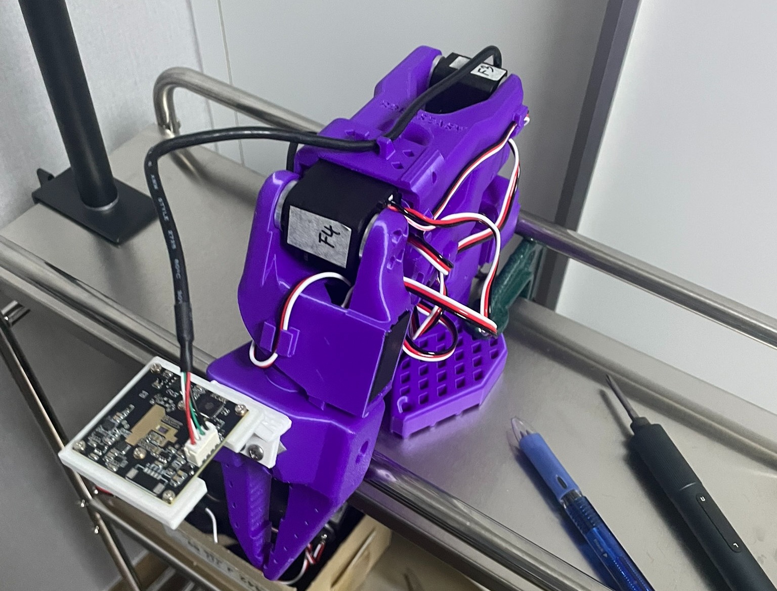
If you're trying a similar camera, the STL files are in my SO-ARM101 38 × 38 mm camera-mount repository:
- Wrist mount: SO101_wrist_IMX307_38mm.stl
- Original tripod holder: Tripod_IMX307_38mm_quarter20_nut.stl
The current README has the dimensions, required hardware, installation instructions, and any later design revisions. Compare them with your actual module; a matching sensor name isn't a fit guarantee.
At the time of the original post, I'd also bought a tripod mount, but the printed holder needed a 1/4-20 nut that I didn't have yet. So I'd only printed that part—I hadn't installed or tested the tripod setup. That would have to wait for a later update. The wrist installation above was the part I'd actually tried.
This was only a small part, but anyone who's assembled a robot arm has probably met this kind of tiny compatibility surprise. I hope it saves a little trouble for someone else choosing a camera that doesn't fit their 32 × 32 mm mount.
Keep going, and happy building!